In industrial surface preparation, deburring, and finishing operations, the round steel wire brush is a workhorse tool relied upon for consistent rust removal, scale cleaning, and weld conditioning. These brushes operate at high rotational speeds, often exceeding 4,000 RPM on angle grinders and up to 2,000 RPM on larger diameter units mounted on automated processing lines. When functioning correctly, a steel wire round brush delivers uniform contact pressure, predictable material removal rates, and repeatable surface finishes that downstream coating and bonding processes depend on.
Yet vibration remains one of the most frequently reported and operationally disruptive issues with these tools. A vibrating steel wire round brush introduces measurable risks: operator hand-arm vibration syndrome (HAVS) from prolonged exposure, loss of dimensional control over the workpiece, uneven surface treatment that requires rework, accelerated wear on power tool bearings and spindles, and, in severe cases, catastrophic brush failure that launches broken wires at high velocity. A 2023 industry survey of metal fabrication shops found that vibration-related brush problems accounted for approximately 27% of all calls for troubleshooting wire brushes, making it the second most common issue after premature wire breakage. Understanding why vibration occurs—and how to systematically eliminate it—is essential for both shop-floor productivity and workplace safety compliance.
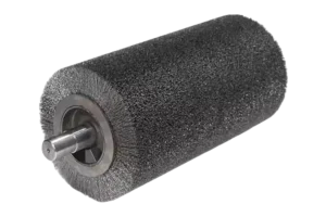
Steel wire round brush vibration is most often caused by one or more of the following: a bent or physically damaged brush body, incorrect mounting on the arbor or spindle, uneven wire wear across the brush face, loose or broken individual wires creating rotational imbalance, debris accumulation inside the brush hub, operating at speeds exceeding the brush’s rated maximum RPM, or applying uneven pressure during use. In the majority of cases, vibration can be eliminated through systematic inspection, proper mounting technique, speed verification, and timely replacement of compromised brushes.
The troubleshooting process does not require specialized diagnostic equipment in most cases. A disciplined, step-by-step approach—starting with a visual inspection and progressing through mounting checks, speed verification, and operational technique adjustments—resolves the vast majority of vibration complaints within minutes. The following sections break down each root cause in detail, explain the underlying mechanics of why each factor induces vibration, and provide actionable remediation steps that maintenance teams and operators can implement immediately. Throughout this guide, the discussion applies not only to hand-held power tool applications but also to automated and semi-automated production environments where cylinder rotary brush configurations are deployed in continuous processing lines.
Why Does My Steel Wire Round Brush Vibrate During Operation
Vibration in a steel wire round brush occurs when the brush’s center of mass deviates from its axis of rotation, creating an eccentric load that generates cyclic forces proportional to the square of the rotational speed. Even a mass imbalance as small as 0.5 grams at 8,000 RPM can produce a centrifugal force exceeding 3.5 newtons—enough to cause perceptible handle vibration and measurable runout at the brush perimeter.
The physics governing brush vibration are straightforward but often underappreciated on the shop floor. When a rotating body’s mass distribution is not perfectly symmetric around its spin axis, the resulting imbalance generates a force vector that rotates with the brush. This force is transmitted through the spindle, bearings, tool housing, and ultimately into the operator’s hands. The magnitude of this force scales with the square of angular velocity, which explains why a brush that feels acceptable at 3,000 RPM may become dangerously unstable at 6,000 RPM.
Several distinct mechanisms can introduce mass asymmetry into a wire brush system. The first and most obvious is physical deformation of the brush body. A brush that has been dropped onto a concrete floor, struck against a workpiece edge, or stored with heavy objects resting on it may develop a bent hub or distorted wire profile. Even deformations invisible to the naked eye—on the order of 0.1 to 0.3 millimeters of runout at the brush perimeter—can generate significant vibration at operating speed. A metal cylinder brush with a precision-machined hub and balanced wire distribution is inherently less susceptible to this type of imbalance than lower-quality alternatives where manufacturing tolerances are looser.
The second mechanism involves wire loss or uneven wire wear. As individual wire filaments fracture and detach during use, the mass distribution around the brush circumference changes. This effect is cumulative: a brush that has lost 15 to 20 wires from one quadrant while retaining full density elsewhere will develop a measurable imbalance. Loose wires that have not yet fully detached can shift position during rotation, creating a dynamic imbalance that changes in severity as the brush accelerates and decelerates.
The following table summarizes the primary imbalance mechanisms and their typical severity:
For operations where vibration control is particularly critical—such as automated deburring cells or precision surface finishing—selecting a well-balanced cylinder rotary brush designed for continuous high-speed rotation can dramatically reduce imbalance-related downtime and rework.
What Are the Most Common Causes of Wire Brush Vibration
The five most common root causes of wire brush vibration are (1) incorrect mounting that leaves the brush not fully seated on the spindle shoulder, (2) operating above the brush’s maximum rated RPM, (3) applying excessive or uneven pressure during use, (4) using a brush with accumulated debris or wire fragments in the hub, and (5) continuing to run a brush that has sustained physical damage or developed uneven wire wear from previous misuse.
Incorrect Mounting and Its Consequences
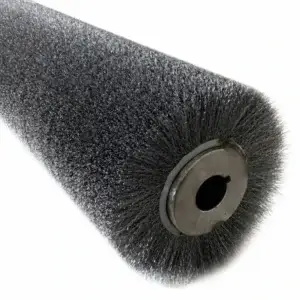
Improper mounting is the single most frequently overlooked cause of brush vibration, and it is also the easiest to correct. When a brush is threaded onto an angle grinder spindle but not tightened fully against the spindle shoulder, even a gap of 0.5 millimeters misaligns the brush’s rotational axis with the spindle. The result is a wobble that increases in amplitude as speed rises.
Key mounting checks that should become standard procedure:
- Verify that the spindle thread direction matches the brush hub thread. Most angle grinders use an M14 thread, but variations exist across manufacturers and regions.
- Ensure the brush is threaded completely until the hub face makes firm contact with the spindle shoulder. A brush that stops 1–2 turns short of full seating will wobble.
- Verify that the spindle shoulder and brush hub mating surfaces are clean and free of debris, corrosion, or burrs that could prevent flush contact.
- For arbor-mounted cylinder brushes used in automated equipment, confirm that the keyway is engaged and the set screws are torqued to specification.
- After mounting, run the tool at low speed for 5–10 seconds and observe the brush perimeter for visible runout before applying it to the workpiece.
Operating Above Rated Speed
Every wire brush has a maximum safe operating speed, typically stamped on the hub or packaging. This rating is determined by the brush diameter, wire gauge, hub material strength, and the dynamic balancing performed during manufacturing. Exceeding this speed generates centrifugal forces that not only amplify any existing imbalance but can also cause wires to permanently deform outward, creating a new imbalance that persists even after speed is reduced.
The relationship between speed and centrifugal force is quadratic: doubling the RPM quadruples the centrifugal force. A brush rated for a maximum of 4,500 RPM that is run at 6,000 RPM experiences approximately 78% higher centrifugal loading than its design limit. At these elevated forces, the risk of wire fatigue, hub deformation, and catastrophic failure increases substantially. For applications requiring sustained high-speed operation, you should select a high-speed compatible wire brush for rust removal that is specifically engineered for elevated RPM ranges, rather than pushing a standard brush beyond its rating.
Excessive or Uneven Pressure
Operators sometimes compensate for a dull or unsuitable brush by applying more pressure, under the assumption that harder contact will improve cleaning speed. In reality, only the tips of the wire filaments should contact the workpiece. When excessive pressure is applied, the wires bend laterally, losing their cutting action and instead dragging across the surface. This lateral deflection is rarely uniform across the brush face, creating uneven loading that manifests as vibration.
The correct technique is to let the brush weight and tool RPM do the work. A properly selected rust removal brush with appropriate wire gauge and density for the substrate will remove corrosion and scale efficiently with light, consistent contact pressure. Operators should be trained to recognize the feel and sound of a brush working at its optimal pressure: steady, consistent contact without bogging or chatter.
Debris Accumulation and Wire Fragment Entrapment
During use, small fragments of removed material—scale, rust particles, and paint chips—can become lodged between the wire filaments and inside the brush hub. Over time, this debris accumulates asymmetrically, adding mass to one side of the rotating assembly. Additionally, broken wire tips that detach from the filament bundle but remain trapped within the brush body can shift position during rotation, creating a dynamic imbalance that is difficult to diagnose because it may not be present when the brush is stationary.
Regular cleaning after each shift or major job should include:
- Tapping the brush gently against a wooden surface to dislodge loose particles.
- Using compressed air (at a safe distance and with appropriate PPE) to blow out debris from between the wire filaments.
- For cup brushes, inspect the inside of the cup cavity for accumulated debris and remove it with a non-metallic scraper or brush.

How Do I Properly Mount a Steel Wire Round Brush to Prevent Vibration
Proper mounting requires threading the brush fully onto the spindle until the hub seats flush against the spindle shoulder, verifying the thread direction matches the tool, cleaning both mating surfaces before assembly, and performing a 10–15 second low-speed run-in test while observing for visible runout before applying the brush to the workpiece.
Detailed Mounting Procedure
The mounting procedure begins before the brush ever touches the spindle. First, inspect the spindle threads for damage, corrosion, or debris. Damaged threads can prevent the brush from seating fully, and even minor thread deformation can introduce a slight angular misalignment that grows into significant vibration at speed. If the spindle threads show galling or flattening, the tool should be serviced before further use.
Second, inspect the brush hub. The threaded insert or arbor hole should be clean and free of burrs. For brushes that have been previously mounted and removed, check for thread damage that may have occurred during removal, particularly if the brush was overtightened or removed using excessive force.
The actual mounting sequence for angle grinder applications:
- Ensure the tool is unplugged or the battery is removed.
- Depress the spindle lock button and hold it firmly.
- Thread the brush onto the spindle by hand, turning in the direction indicated on the brush or tool. Most angle grinders use a spindle direction where the brush tightens during operation, so the mounting direction may be counterclockwise.
- Continue hand-threading until the brush hub contacts the spindle shoulder. Do not use the spindle lock to wrench-tighten the brush beyond hand-tight; the rotational inertia during startup and operation will self-tighten the brush further.
- Release the spindle lock. Gently attempt to rotate the brush by hand in the loosening direction to confirm it is seated and cannot be backed off without depressing the spindle lock.
- Reconnect power and run the tool at its lowest speed setting for 10–15 seconds, holding it in a protected orientation away from the body and any bystanders. Observe the brush perimeter against a fixed reference point to assess runout.
- If no visible wobble is detected, increase the speed to operating speed and observe again before contacting the workpiece.
Mounting for Automated and Inline Cylinder Brush Systems
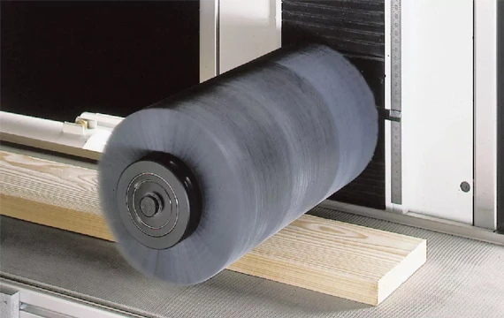
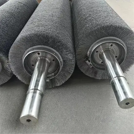
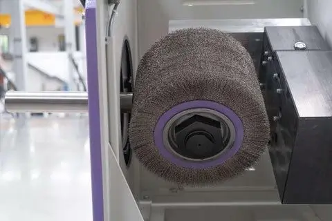
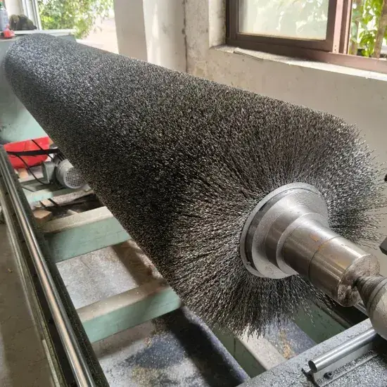
For cylinder rotary brush configurations used in production machinery, the mounting procedure differs from hand-held tools. These brushes typically mount on a driven shaft with keyway engagement and set screw or clamp collar retention.
Critical steps for inline cylinder brush mounting:
- Verify the shaft diameter matches the brush core bore within specified tolerance (typically H7/g6 or similar fit).
- Ensure the key fully engages both the shaft keyway and the brush core keyway with no more than 0.05 mm of circumferential play.
- Tighten set screws in a cross-pattern sequence to the torque specified in the equipment manual. Uneven set screw torque can displace the brush core off-center.
- After mounting, rotate the shaft by hand through at least three full revolutions and measure radial runout at both ends of the brush using a dial indicator. Runout should not exceed 0.1 mm total indicated runout (TIR) for precision applications.
- For multi-brush assemblies on a common shaft, stagger the brush mounting orientations so that any residual imbalance in individual brushes tends to cancel rather than accumulate.

How Do Wire Material and Brush Design Affect Vibration Tendency
Wire material selection and brush design parameters—including wire diameter, density, winding pattern, and hub construction—directly influence a brush’s susceptibility to vibration. Brushes with higher wire density and precision-wound filaments exhibit greater inherent balance, while those with inconsistent wire distribution or lower-quality hub machining are more prone to imbalance from the outset.
Wire Material Considerations
Different wire materials exhibit different mechanical properties that affect how the brush behaves during operation and how it responds to wear. Carbon steel wire, the most common material for general-purpose steel wire round brushes, offers high cutting aggressiveness and moderate fatigue resistance at moderate cost. However, carbon steel is susceptible to corrosion if stored improperly, and rust formation on the wire surface can alter mass distribution and introduce imbalance over time.
Stainless steel wire brushes provide superior corrosion resistance and are preferred for applications involving stainless steel workpieces or wet environments. The wire itself is slightly less stiff than carbon steel of the same diameter, which can affect cutting performance but also means the wires are less prone to brittle fracture and sudden mass loss during use.
Brass wire brushes are used for softer surfaces and places where sparks aren’t a problem. Brass has higher density than steel (approximately 8.5 g/cm³ versus 7.8 g/cm³), which means that brass wire brushes carry more mass at the perimeter for a given wire count and diameter. This higher rotating mass can amplify the effects of any imbalance present.
The table below compares key wire material properties relevant to vibration behavior:
Design Factors That Improve Balance
Brush manufacturers employ several design strategies to minimize inherent imbalance and improve vibration resistance. Wire-wound cylinder brushes, where filaments are continuously wound in a helical pattern around the core, typically exhibit better balance than tufted or knotted configurations because the wire mass is distributed more uniformly around the circumference.
Hub construction also plays a significant role. A hub machined from solid bar stock with concentricity held to tight tolerances (0.02 mm TIR or better) provides a more stable foundation than a stamped or pressed hub where dimensional variation is greater. The key advantages of using metal cylinder brush configurations in production environments include their inherently superior balance characteristics, which translate directly into reduced vibration, longer bearing life on driven equipment, and more consistent surface finish quality across extended production runs.
Wire density—the number of wire filaments per unit area of the brush face—is another critical parameter. Higher-density brushes distribute mass more evenly and are less affected by the loss of individual wires during use. A brush with 80% fill density that loses 10 wires experiences a smaller relative mass change than a brush with 50% fill density losing the same number of wires.
What Preventative Maintenance Practices Reduce Brush Vibration
Effective preventative maintenance for wire brushes centers on five practices: pre-use visual inspection for damage and wire condition, proper cleaning and dry storage after each use, periodic run-in testing to detect emerging imbalance, adherence to speed and pressure limits during operation, and timely replacement of brushes that show signs of uneven wear, loose wires, or hub deformation.
Establishing a Brush Inspection Protocol
A structured inspection routine eliminates the guesswork from brush maintenance decisions. The following daily and weekly inspection points should be documented as part of standard operating procedures:
Daily inspection (before first use and between jobs):
- Examine the brush perimeter under good lighting for missing, bent, or flattened wires. Any quadrant showing visibly lower wire density than the rest of the brush indicates uneven wear.
- Check for loose wires by gently flexing small sections of the wire bundle. Wires that move independently or can be pulled free with minimal force are candidates for detachment during operation.
- Inspect the hub for cracks, deformation, or thread damage. A cracked hub is an immediate replacement trigger regardless of wire condition.
- For cup brushes, look inside the cup cavity for debris accumulation.
- Verify that the maximum RPM marking on the brush is still legible and compare it against the tool’s rated speed.
Weekly inspection (or every 40 operating hours, whichever occurs first):
- Measure brush diameter with calipers and compare against the original specification. A brush that has worn down to less than 70% of its original diameter should be replaced, as the reduced wire length alters the brush dynamics.
- Perform a run-in test on a known-good tool and assess vibration level subjectively. Any increase from the baseline established when the brush was new warrants closer investigation.
- It’s important to document the condition of the brushes and to replace them on a schedule instead of waiting for failure.
Storage Practices That Preserve Balance
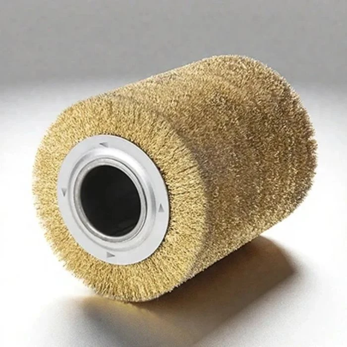
How brushes are stored between uses has a direct impact on their balance characteristics when next deployed. Brushes should be stored:
- In a clean, dry environment with controlled humidity (below 60% relative humidity to prevent corrosion of carbon steel wire).
- Brushes should be hung or stored standing upright, not stacked or piled, to prevent the weight of other tools from deforming the wire profile or hub.
- Protected from impact and crushing by dedicated storage racks or compartments.
- Store carbon steel brushes in sealed containers with desiccant packets for long-term storage.
Replacement Triggers
Knowing when to retire a brush is as important as knowing how to use one. The following conditions should trigger immediate replacement:
- Visible hub cracking, deformation, or thread damage.
- Wire density in any quadrant reduced by more than 25% compared to the densest quadrant.
- Persistent vibration after remounting, cleaning, and speed verification on a different tool.
- Brush diameter worn below 70% of the original specification.
- Any incident where the brush has been dropped from a height greater than 1 meter onto a solid surface.
Frequently Asked Questions
Q1: Can a slightly vibrating brush still be used safely?
Do not ignore mild vibration, but immediate replacement is not always necessary. Remount the brush and make sure it is fully seated on the spindle shoulder. Run at low speed for 15 seconds and check whether vibration settles. If it persists after remounting and cleaning, the brush likely has imbalance from uneven wear or damage—replace it. Continued use accelerates bearing wear and increases operator fatigue.
Q2: Does the diameter of a steel wire round brush affect vibration?
Yes. Larger-diameter brushes have more mass at a greater radius, so the same imbalance produces higher centrifugal force. A 150 mm brush with the same percentage imbalance as a 75 mm brush generates about 4× the vibration force at the same RPM. Larger brushes require tighter tolerances and more careful mounting. Confirm the tool is rated for the brush diameter; an oversized brush on a small or underpowered grinder compounds vibration risk.
Q3: What is the difference between static and dynamic imbalance?
Static imbalance: the center of mass is displaced from the rotational axis, so the brush rotates to a consistent heavy spot on a balancing arbor. It vibrates at the rotational frequency and stops immediately when powered off.
Dynamic imbalance: mass asymmetry along the brush’s axial length creates a rocking couple only during rotation. It may vibrate at harmonics and show perimeter wobble that changes with speed.
Most field vibration is a combination of both, with static imbalance dominant.