Industrial rotating equipment runs on a simple rule: what spins must spin true. When a metal coil brush operates at several hundred or even a few thousand RPM, even a few grams of imbalance translate into forces measured in kilograms pushing sideways on the shaft. Maintenance teams see the aftermath — bearings that should last 20,000 hours failing at 5,000, housings that run hot to the touch, and production lines stopped for unplanned changeouts. Few trace the problem back to the brush itself.
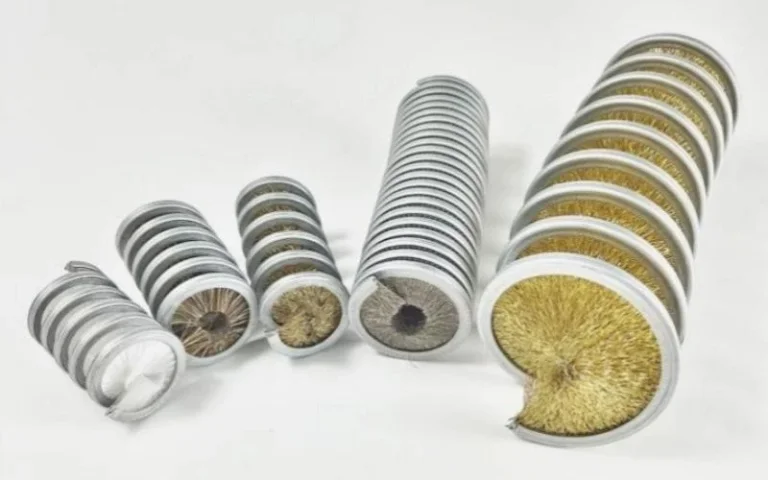
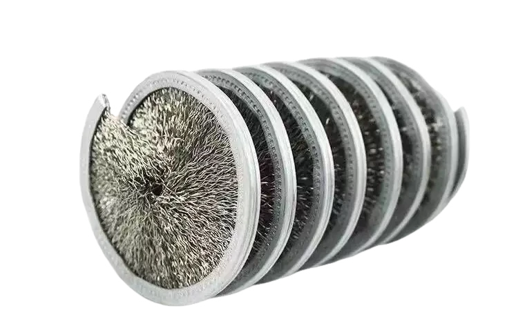
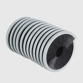
The issue hides in plain sight. A steel coil brush looks simple — wire wound around a core — but its mass distribution is never perfect. Manufacturing tolerances, uneven filament wear during service, and contamination buildup all shift the center of mass away from the rotational axis. Once that shift happens, every revolution pumps destructive energy into the support bearings—the damage compounds silently until something gives.
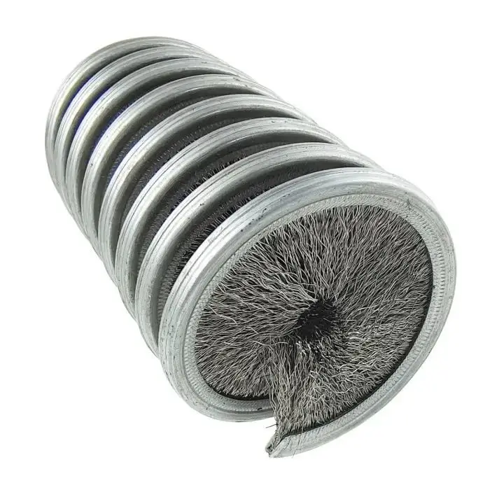
An unbalanced metal coil brush generates radial forces proportional to the square of its rotational speed. These forces are transmitted directly through the shaft to the rolling elements of support bearings, causing brinelling, fatigue spalling, and accelerated wear that can cut bearing life by 50% to 80% compared to properly balanced operation. The failure mode is progressive: early-stage vibration widens bearing clearances, which in turn amplifies the imbalance effect, creating a feedback loop that ends in catastrophic bearing collapse.
Most maintenance schedules account for normal bearing wear. Very few account for the extra load a vibrating brush imposes. A standard deep-groove ball bearing rated for 30,000 hours at a given load might deliver those hours if the load stays constant. But vibration introduces cyclic loading — peaks and valleys at frequencies tied to RPM — and bearing fatigue life drops exponentially with load increase, not linearly. A 10% increase in dynamic load can halve the bearing’s L10 life. When your outside coil brush shakes the housing, the bearings are absorbing far more than 10%.
The good news: imbalance is measurable, correctable, and preventable. Unlike chemical wear or thermal degradation, mechanical imbalance leaves clear signatures in vibration spectra long before bearings fail. The challenge is recognizing those signatures and acting on them before the maintenance window closes.
What Causes Imbalance in a Metal Coil Brush
Imbalance in a metal coil brush comes from three main sources: manufacturing eccentricity (the center of mass does not align with the bore axis), uneven filament wear during service, and material buildup from process contamination. Any of these alone can push vibration past acceptable limits; combined, they accelerate bearing damage dramatically.
1. Manufacturing Eccentricity — The Hidden Defect in New Brushes
Manufacturing a coil brush means winding wire around a mandrel or core. The winding process, however precise, introduces small variations in wire tension and filament distribution. A research review from brushcustom.com notes that even brand-new brush rollers can carry residual imbalance from the production stage — wire density varies slightly along the coil length, and core straightness tolerances stack up. For a brush running at 1,800 RPM, a mass eccentricity of just 5 grams at a radius of 30 mm produces roughly 5.3 newtons of centrifugal force. That force reverses direction 30 times every second, hammering the bearing race each cycle.
2. Uneven Filament Wear — Imbalance That Develops Over Time
Field conditions make it worse. As the brush contacts workpieces or conveyor surfaces, filaments wear down. The wear is rarely uniform. If the brush engages more heavily on one side — common in applications where the workpiece enters from a fixed direction — filaments shorten faster on that side. Within weeks of continuous operation, a brush that started balanced can develop significant mass asymmetry.
3. Contamination Buildup — The Overlooked Contributor
Contamination adds another variable. In metalworking environments, the brush picks up cutting fluid residue, metal fines, and scale particles. These materials accumulate in the coil gaps. Dense accumulations on one side of the brush shift the mass center. The effect is most pronounced on stainless steel wire coil brush units running in wet or oily conditions, where contaminants stick and compact rather than falling away.
How Vibration from an Unbalanced Coil Brush Damages Bearings
Vibration from an unbalanced coil brush damages bearings through three mechanisms: surface fatigue from cyclic overload, false brinelling from stationary vibration, and lubricant film breakdown under impact loading. The first mechanism dominates in running conditions; the second occurs during idle periods when nearby equipment transmits vibration through the machine frame; the third accelerates wear once clearances open up.
Lubricant Film Breakdown — When Microns Make the Difference
Rolling element bearings depend on a thin lubricant film separating balls or rollers from raceways. That film is typically 0.1 to 0.5 microns thick — thinner than a human hair. When an unbalanced brush applies a cyclic radial load, the load zone within the bearing shifts with each revolution. Rolling elements entering and leaving the load zone experience rapid pressure changes. At the entry point, the lubricant film can collapse momentarily, allowing metal-to-metal contact.
Surface Fatigue and Spalling — The Domino Effect of Repeated Contact
Repeated metal-to-metal contact initiates microscopic cracks below the raceway surface. These cracks propagate with continued cycling until small pieces of material spall away, leaving pits. Once pitting starts, vibration levels climb sharply because the rolling elements now bounce across damaged surfaces. The transition from smooth operation to audible roughness can happen in a matter of hours once spalling begins.
False Brinelling — Damage That Happens While the Machine Is Off
Stationary vibration causes its own damage pattern. When a machine sits idle but adjacent equipment runs — common in multi-line production facilities — vibration transmits through the floor and frame into the brush shaft bearings. The rolling elements, stationary in their positions, fret against the raceways in a small rocking motion. This wears shallow depressions matching the ball or roller spacing, a condition called false brinelling. When the machine restarts, those depressions produce rhythmic noise and accelerate fatigue.
The relationship between vibration velocity and bearing life follows documented curves. ISO 10816-3 provides vibration severity zones for industrial rotating equipment. Below 1.8 mm/s RMS, most bearings achieve their design life. Between 1.8 and 4.5 mm/s, life reduction becomes measurable. Above 4.5 mm/s, bearing life drops below 50% of its rating, and failures become unpredictable.
The Real Cost of Premature Bearing Failure in Industrial Operations
Premature bearing failure driven by brush imbalance costs more than replacement bearings and labor. The larger expense comes from unplanned downtime, collateral damage to shafts and housings, quality defects from inconsistent brush contact, and higher energy consumption as bearings degrade. A single bearing failure on a critical line can cost $5,000 to $50,000 per hour of lost production.
The Hidden Expense Beyond Replacement Parts
When maintenance teams replace bearings without addressing the imbalance that killed them, the new bearings face the same overload. Facilities that run through three or four bearing sets per year on the same brush station are not seeing random failures. They are seeing a root cause they have not yet measured.
Collateral damage multiplies the bill. A bearing that seizes can spin the outer race in its housing, machining away the housing bore until it no longer holds a proper interference fit. Shaft journals score under a seized inner race. What starts as a $200 bearing replacement becomes a $3,000 shaft and housing repair. On large-diameter brush assemblies where the shaft is integral to the machine frame, housing damage can require complete teardown.
Quality Loss and Throughput Reduction
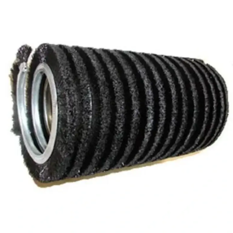
Product quality takes a hit too. A vibrating brush cannot maintain consistent contact pressure with the workpiece. On a coil cleaning brush application where surface finish matters — tube descaling, wire cleaning, deburring — vibration translates into uneven material removal. Operators compensate by slowing the line or running rework passes, both of which reduce throughput.
Energy Waste — The Silent Cost Accumulation
Energy consumption rises as bearings degrade. A deep-groove ball bearing in good condition has a friction coefficient around 0.0015. As spalling develops, that number can triple or quadruple. For a 5 kW drive motor running a brush assembly, a bearing efficiency drop from 99.5% to 98% adds roughly 75 watts of continuous extra load. Over 6,000 operating hours per year, that is 450 kWh wasted — small per unit, but significant across a plant with dozens of rotating assemblies.
The financial picture across a typical year for one unbalanced brush station:
Best Practices for Maintaining Metal Coil Brush Balance
Maintaining metal coil brush balance requires a combination of proper installation procedures, scheduled vibration monitoring, contamination management, and timely filament replacement before wear patterns create significant asymmetry. The most effective programs balance brushes at installation, check vibration monthly, clean coils during each maintenance cycle, and replace brushes when filament loss exceeds 15% of the original diameter.
Installation and Balancing — Getting the Starting Point Right
Installation sets the baseline. Before mounting a new brush, check the bore and shaft for cleanliness. A speck of debris between the brush hub and shaft shoulder can introduce enough runout to create measurable imbalance. Use a dial indicator on the brush OD after mounting: total indicated runout should not exceed 0.1 mm for brushes running above 1,000 RPM. If the brush itself runs true but vibration persists, the shaft may be bent or the bearings already damaged from the previous brush.
Balancing a coil brush follows the same principles as balancing any rotor. The brush can be balanced on a dedicated balancing machine or in place using trial weights. For in-place balancing, take a baseline vibration reading, attach a known trial weight at a marked angular position, measure the change in amplitude and phase, and calculate the correction weight and position. Most industrial brushes require only single-plane balancing since the brush length is short relative to its diameter.
Cleaning and Contamination Control — Preserving Mass Symmetry
Cleaning matters more than most operators realize. A coil brush that accumulates debris unevenly will vibrate, regardless of how well it was balanced at installation. A cleaning schedule tied to the specific process conditions — more frequent in wet or sticky environments, less frequent in dry dust — prevents contamination from becoming an imbalance driver. Compressed air at moderate pressure (below 4 bar to avoid filament damage) clears loose debris. For caked-on deposits, a solvent soak followed by a low-pressure rinse restores mass symmetry.
Wear Monitoring and Replacement Timing — Knowing When to Retire a Brush
Filament wear monitoring ties directly to bearing protection. When filaments on a brush wear to approximately 85% of their original length, the brush should come out for measurement. A brush with uneven wear should be replaced, not rotated — rotating a worn brush does not correct the mass imbalance; it just moves the heavy spot to a different angular position. For selecting brass coil brushes in applications where filament wear is inherently uneven, specifying a slightly softer filament material may extend the balanced service interval by allowing the brush to brush more uniformly.
Documentation closes the loop. A simple log tracking installation date, initial vibration reading, monthly trending values, cleaning dates, and replacement dates turns chaotic reactive maintenance into a predictable schedule. When the data shows that a particular brush position consistently drifts out of balance after six weeks of operation, replacement can be scheduled for week five — before vibration damages the bearings.
Maintenance teams that follow these practices see bearing life return to catalog ratings. The investment is modest: a vibration meter, a dial indicator, cleaning supplies, and 30 minutes of technician time per brush per month. The return is measured in avoided downtime, avoided bearing purchases, and consistent product quality.
Inspection and Maintenance Checklist
- Measure and record radial vibration at each bearing housing: monthly minimum
- Check brush OD runout with dial indicator: at installation and after any disassembly
- Clean coil gaps to remove process debris: frequency matched to process contamination rate
- Inspect filament length uniformity: every two weeks or 100 operating hours
- Measure bearing housing temperature: weekly
- Replace brush when filament loss exceeds 15%, or vibration exceeds 3 mm/s RMS
- Document all readings in equipment maintenance log
FAQ
How do I know if vibration is coming from the brush or from the motor?
Disconnect the brush from the motor and run the motor alone. If vibration drops to normal levels, the brush is the source. If vibration persists without the brush, the motor or coupling needs investigation. A spectrum analyzer makes this even clearer: brush imbalance produces a pure 1× RPM peak in the radial plane, while motor electrical issues often show peaks at line frequency (50/60 Hz) and its harmonics.
Can I balance a coil brush myself without sending it to a shop?
Yes, in-place single-plane balancing is a common field procedure. You need a vibration meter that reads amplitude and phase, a set of trial weights, and a protractor or angle marking on the brush hub. The process takes about 30 to 60 minutes per brush once the technique is familiar. Most industrial maintenance teams handle this in-house.
Does brush diameter affect how critical balance is?
Absolutely. Centrifugal force scales with radius, so a larger-diameter brush at the same RPM produces proportionally more force for the same mass imbalance. A 200 mm diameter brush with 5 grams of imbalance at 1,500 RPM generates roughly twice the radial force of a 100 mm brush with the same imbalance at the same speed. Large-diameter brushes on high-speed lines deserve the most attention in any balancing program.